Mechanical Engineering Articles
Best 9 Opportunities for Mechanical Engineers in India's EV Industry
How 3D Rendering is evolving Mechanical Product Design? Interesting Facts to Read!
What is CAM (Computer-Aided Manufacturing)?
Generative Design: Navigating the Future of Mechanical Engineering

Get In Touch For Details! Request More Information
Engineering Drawing Basics Explained [Bonus Tips Included]
Jan 24, 2024 5 Min Read 1331 Views
(Last Updated)
Have you ever wondered how engineers share their ideas and designs with the world? The answer lies in the art of engineering drawing. This blog is here to guide you through the essentials of engineering drawings, a fundamental tool in the world of engineering and manufacturing.
We’ll start by explaining what an engineering drawing is. We’ll look at the different parts of these drawings, like the kinds of lines used and the different views (like looking at something from the top, side, or front). We’ll also talk about different kinds of engineering drawings. Plus, we’ll share some helpful tips on how to make these drawings better.
These tips and explanations will help you get better at engineering drawing. Let’s start learning!
Table of contents
- What is Engineering Drawing?
- Basic Components of an Engineering Drawing
- Different Types of Lines
- Types of Views
- Types of Engineering Drawings
- Assembly Drawings
- Part Drawings
- Schematic Drawings
- Sectional Drawings
- Site Plans
- Elevation Drawings
- Piping and Instrumentation Diagrams (P&ID)
- Electrical Diagrams
- Important Tips for Improving Engineering Drawing
- Conclusion
- FAQs
- What are the most important types of lines I should know in engineering drawing?
- Why are different views like orthographic, isometric, and sectional important in engineering drawings?
- What are some key tips for improving my engineering drawings?
What is Engineering Drawing?
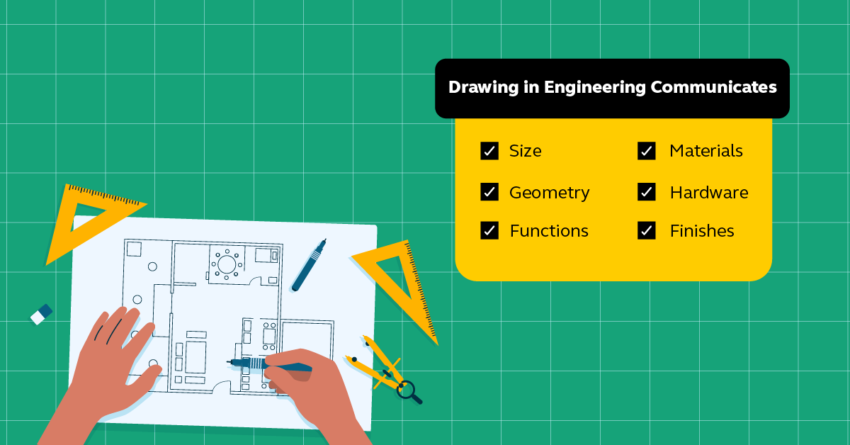
Engineering drawing is a specialized form of communication that uses a strict set of symbols, standards, and perspectives to depict mechanical, electrical, or structural designs. These drawings are essentially the blueprints or plans for manufacturing a wide array of products and structures.
The role of engineering drawing in conveying technical information is crucial. It serves as a universal language that bridges the gap between engineers’ conceptual ideas and the practical world of manufacturing and construction. Through these drawings, engineers can accurately communicate the dimensions, materials, and assembly instructions necessary to construct a product or structure.
In the manufacturing process, engineering drawings are used to ensure that every piece of a product is made to exact specifications. This precision is important for the functionality, safety, and quality of the final product. For example, in mechanical engineering, these drawings detail the exact size, shape, and features of mechanical components, while in civil engineering, they provide the layout and specifications for constructing buildings and infrastructure.
Engineering drawings are the foundation upon which products and structures are built, ensuring that what is imagined can be accurately and safely realized in the physical world.
Now that we have a clear understanding of what engineering drawing is, let’s get into the essential building blocks of an engineering drawing.
Basic Components of an Engineering Drawing
The basic components of an engineering drawing can be broadly categorized into two main areas: types of lines and types of views. Each of these plays an important role in conveying specific information about the object being designed or constructed.
Different Types of Lines
- Solid Lines: These are the most commonly used lines in engineering drawings. They represent the edges, surfaces, or outlines of an object. Solid lines are typically used to depict the visible parts of an object.

- Dashed Lines: Also known as hidden lines, dashed lines are used to represent edges or surfaces that are not visible in a particular view. For example, they might show the edges of an object that are hidden behind other parts.

- Dotted Lines: Often used for center lines or symmetry lines, dotted lines indicate the geometric center of an object or a part. They can also be used to represent the path of movement for moving parts.
- Thin Lines: These are used for various purposes, such as dimension lines (showing the size of an object), extension lines (extending a line on an object to aid in dimensioning), and leader lines (connecting a dimension number or note to a feature).
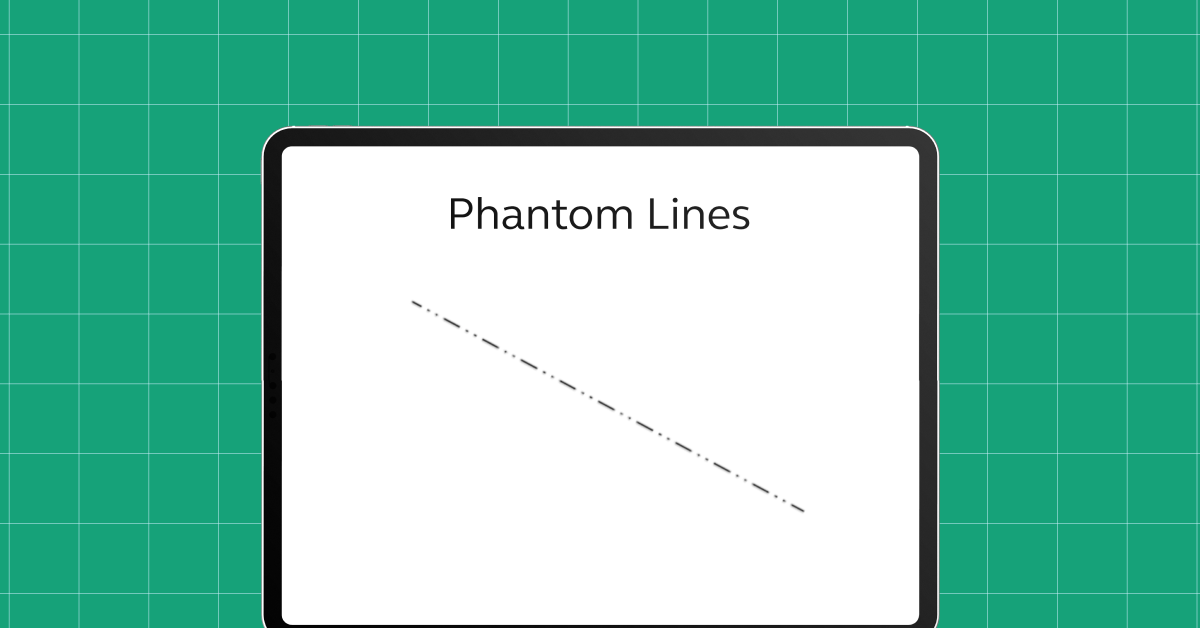
- Phantom Lines: These are used to indicate alternate positions of a moving part or adjacent positions of related parts.

Types of Views
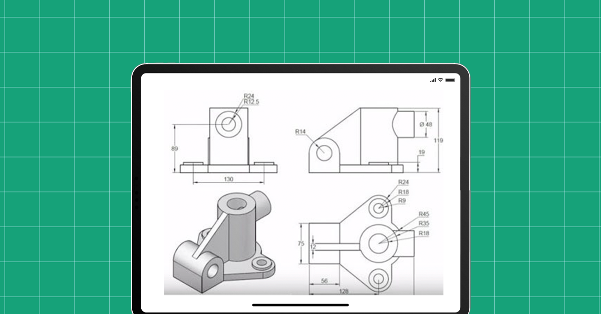
- Orthographic Views: This is the most common type of view used in engineering drawings. Orthographic views represent different sides of an object, typically the top view, front view, and side view. This method provides a comprehensive understanding of the object’s shape and dimensions.
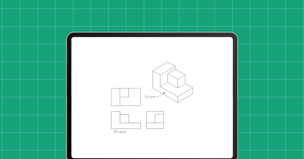
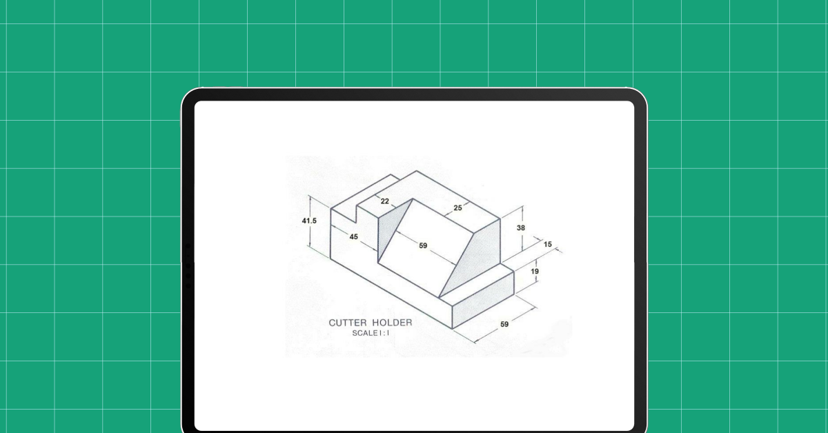
- Isometric View: An isometric drawing represents a three-dimensional view of an object. It helps in visualizing how an object looks from a particular angle. This view is useful for giving a more realistic sense of the object, though it does not replace the precision of orthographic views.
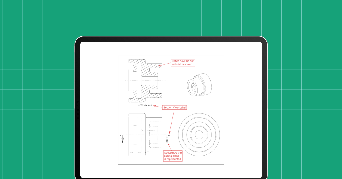
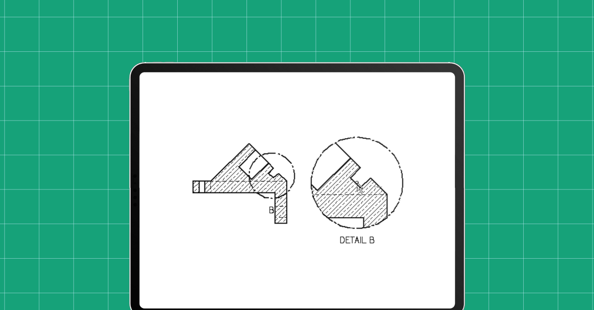
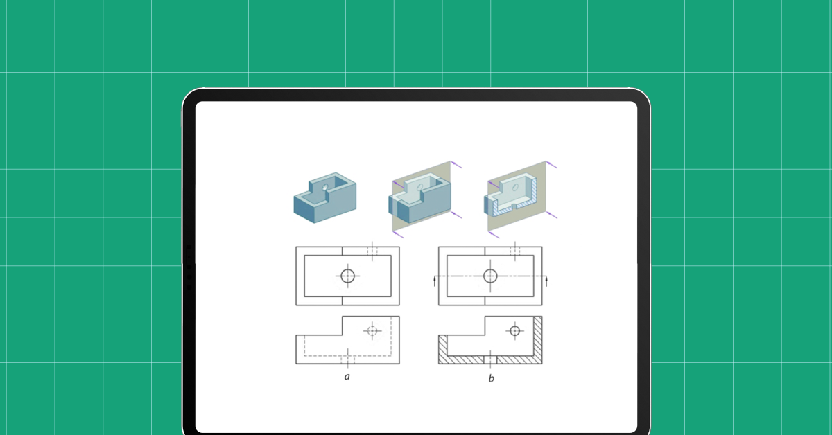
- Sectional View: A sectional view shows an object as if it has been cut through a particular plane. This is particularly useful for showing internal features or complex shapes that are not easily represented in external views.
- Detail View: This view is used to show a small part of the object at a larger scale. It’s particularly useful for highlighting complex or intricate features that might be lost in a larger view.
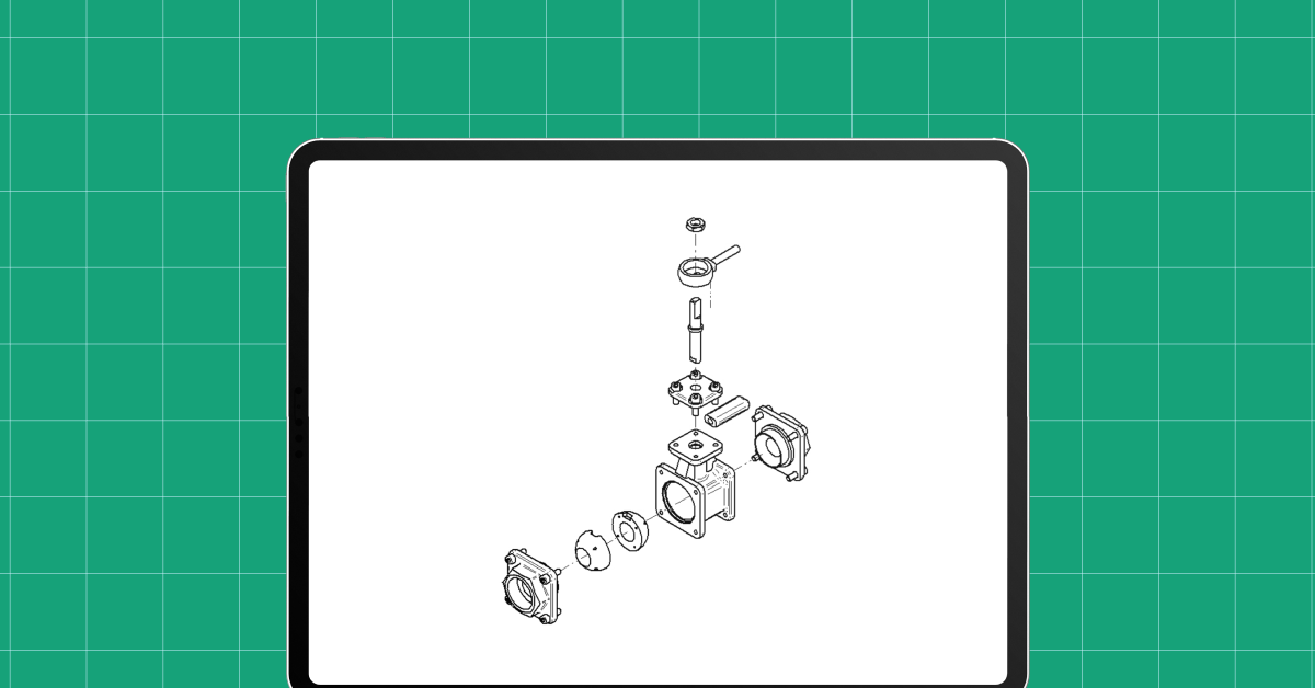
- Exploded View: In this view, the parts of an assembly are separated from each other to show how they fit together. This is especially useful for assembly instructions or maintenance manuals.
Understanding these basic components is essential for anyone looking to read, interpret, or create engineering drawings. Each type of line and view serves a specific purpose, helping to convey the detailed information necessary for accurately building or manufacturing the object or system depicted.
Also Read: 12 Magical Mechanical Engineering Tools in 2024
Having explored the fundamental components of an engineering drawing, let’s now shift our focus to the various types of engineering drawings. These different types serve distinct purposes and are essential tools in the field of engineering. Let’s get into each type to understand its significance and application.
Types of Engineering Drawings
Engineering drawings come in various types, each serving a unique purpose in the design and manufacturing process. Here’s a look at some of the most common types of engineering drawings:
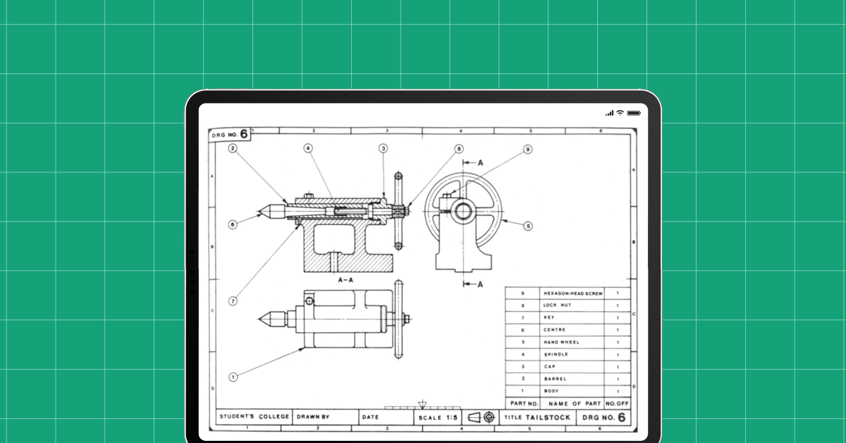
1. Assembly Drawings
These drawings show how multiple parts fit together to form a complete unit. They depict the components of a machine or a system in their relative positions and are essential in guiding the assembly process. The drawing usually includes a bill of materials listing each part.
2. Part Drawings
Also known as detail drawings, these are focused on individual components. A part drawing provides all the necessary information to manufacture the part, including dimensions, materials, and any special manufacturing instructions.
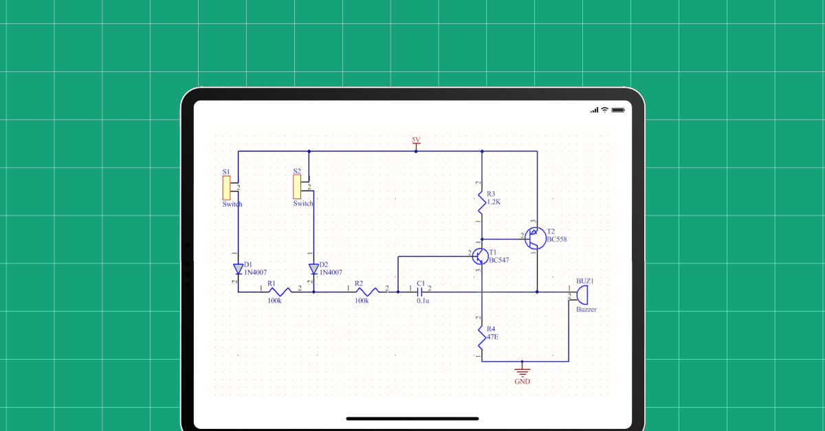
3. Schematic Drawings
Schematics are more about illustrating a concept or system rather than showing precise details. They are commonly used in electrical, hydraulic, and pneumatic systems to represent the connections and flow paths within a system, using standardized symbols.
4. Sectional Drawings
These are used to show ‘inside views’ of complex parts or areas of a product, often where internal features are not visible in other views. They are created by cutting away part of an object to reveal the internal structure.
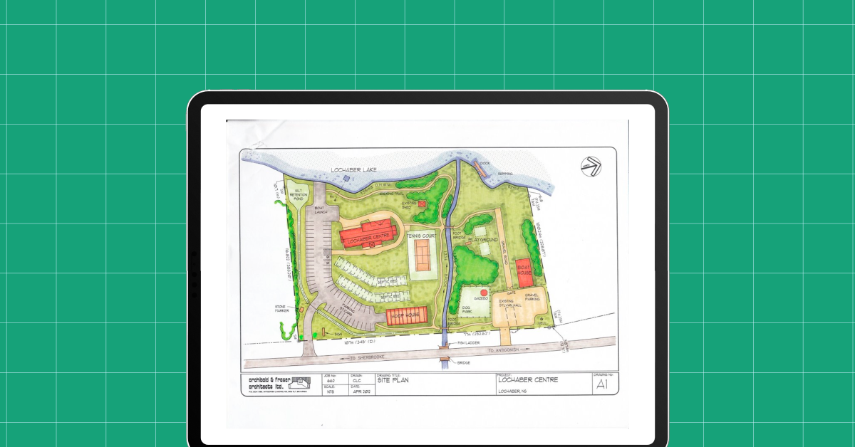
5. Site Plans
In civil engineering, site plans are used to show the entire setting of a project, including boundaries, buildings, and major landscape elements in relation to the surroundings.
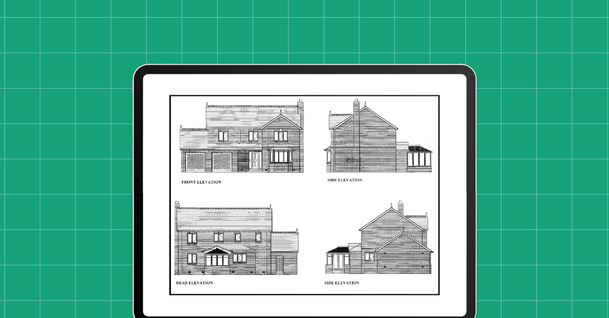
6. Elevation Drawings
Common in architectural and civil engineering, these drawings show the external faces of a building or structure. They provide information about the dimensions and design of the facade.
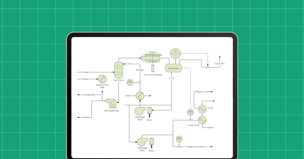
7. Piping and Instrumentation Diagrams (P&ID)
These are essential in process engineering, showing the piping and other components of a physical process flow. They are important for the design and operation of chemical and process plants.
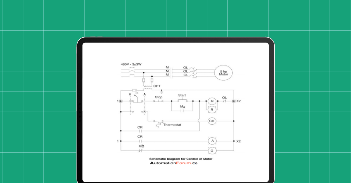
8. Electrical Diagrams
These detail the electrical connections and circuitry, often for consumer electronics, electrical systems in buildings, or complex machinery.
Each type of engineering drawing is designed for a specific purpose from providing a high-level overview of a system (like schematic drawings) to detailing every minute specification needed to manufacture a part (like part drawings). Understanding the purpose and correct application of each type of drawing is key in the engineering field, ensuring precision and efficiency from concept to final product.
Also Read: 8 Important Skills Required for Mechanical Engineering
Now that we’ve looked at different types of engineering drawings, let’s talk about some important tips to make your engineering drawings better.
Important Tips for Improving Engineering Drawing
Improving your engineering drawings can significantly enhance the clarity and usability of your designs. Here are some important tips to consider:
- Include Dimensions of Only Critical and Measurable Features: Focus on dimensioning the critical features of your design. This ensures clarity and precision, making it easier for manufacturers to understand what is essential. Over-dimensioning can lead to confusion and inaccuracies.
- Add Hole Tapping Needs to Your Drawing: Clearly specifying hole-tapping requirements is crucial. This prevents misunderstandings and errors in manufacturing, ensuring that holes are tapped to the correct size and depth for their intended purpose.
- Consolidate Call-Outs: Grouping related information or call-outs can simplify the interpretation of your drawings. This practice makes it easier for the reader to find all the necessary information without having to search through the entire drawing.
- Communicate Assembly Intent of Crucial Features: Clearly indicate how parts should be assembled, especially for crucial features. This communication is key to ensuring that the assembly process is straightforward and error-free.
- Part Numbers are Very Important: Including part numbers helps in efficiently tracking and identifying components. This is especially important in complex assemblies with many parts.
- No Need to Include Optional Secondary Operation Call-Outs: Avoid cluttering your drawing with optional secondary operations unless they are important. This helps keep the drawing focused and clear.
- Avoid Over-Dimension or Over-Tolerance on Your Designs: Excessive dimensioning and over-tolerancing can complicate the manufacturing process and inflate costs. Stick to necessary tolerances that align with manufacturing capabilities.
- Tolerance Must Fall Within Standard Accuracy Levels: Set realistic and achievable tolerances. Unrealistic tolerances can be impossible to achieve in manufacturing, leading to delays and increased costs.
By following these tips, you can create more efficient, clear, and practical engineering drawings, facilitating smoother manufacturing processes and better end products.
Ready to become an AutoCAD expert in mechanical engineering? Enroll in GUVI’s AutoCAD Mechanical Course today! Start your journey to mastering AutoCAD now!
Conclusion
By applying these tips, you can create engineering drawings that are not only more precise and easier to understand but also more practical for real-world applications. Refining your drawing skills can have a significant impact on the success of your projects. Keep these guidelines in mind to improve your engineering drawings, contributing to better design communication and more efficient manufacturing processes.
FAQs
What are the most important types of lines I should know in engineering drawing?
In engineering drawings, understanding different types of lines is important. The most important ones include solid lines (representing visible edges or boundaries of objects), dashed lines (indicating hidden or invisible parts behind other elements), dotted lines (used for centerlines or symmetry), and thin lines (for dimensions, extension, and leader lines).
Each type of line has a specific purpose, helping to communicate different aspects of the design accurately.
Why are different views like orthographic, isometric, and sectional important in engineering drawings?
Different views in engineering drawings provide comprehensive visual information about an object. Orthographic views (like top, front, and side views) offer precise dimensions and shapes from different angles.
Isometric views give a three-dimensional perspective, making it easier to visualize the overall design.
Sectional views are important for revealing the internal features of complex parts. These varied views ensure that all aspects of the design are clearly understood and interpreted correctly.
What are some key tips for improving my engineering drawings?
To improve your engineering drawings, focus on a few key aspects:
Only include essential dimensions, clearly specify hole tapping requirements, consolidate related information for better clarity, clearly indicate assembly details, use part numbers for easy identification, avoid including unnecessary secondary operation details, refrain from over-dimensioning or over-tolerancing, and ensure tolerances are realistic and achievable.
These tips help in creating more accurate, clear, and efficient drawings, facilitating better communication and manufacturing processes.
Career transition


Did you enjoy this article?